
VFD Control Wiring Diagram How to Wire a VFD Variable Frequency Drive YouTube
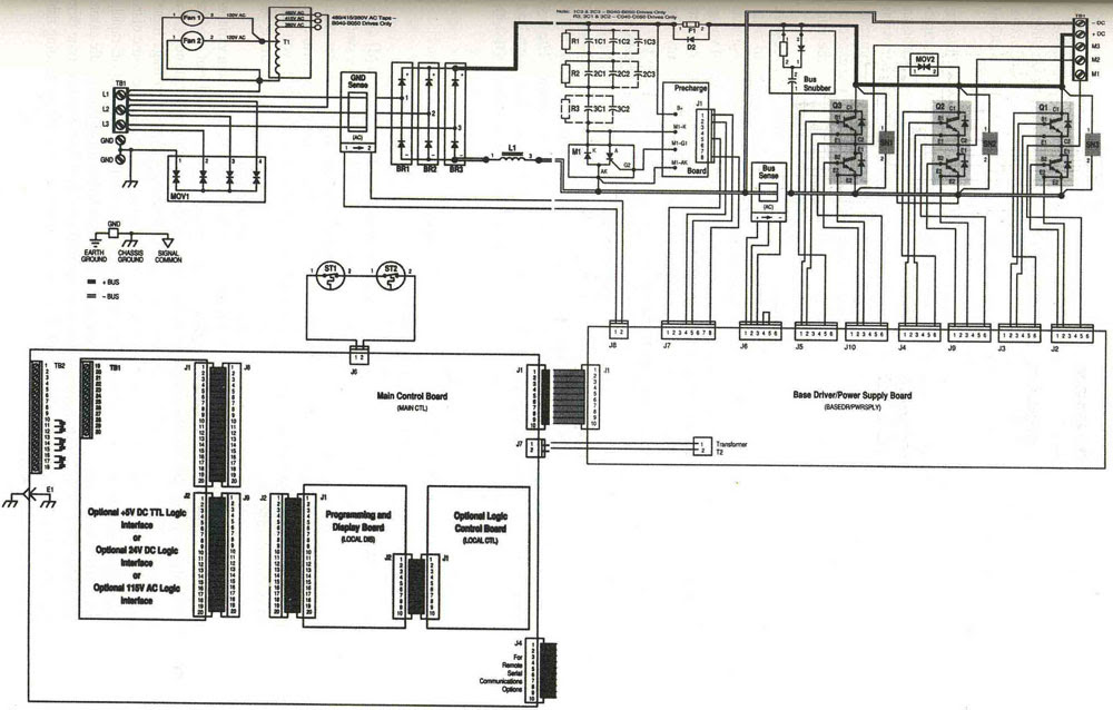
The control circuit is separate from the motor circuit. The control circuit may not be at the same voltage as the power circuit. When the voltage of the control and power circuits is the same, it is referred to as Common Control. If the volt-ages are different, it is called Separate Control. Figure 4. Typical Starter Wiring Diagram — Three-Phase
How to Control VFD with PLC using Ladder Logic InstrumentationTools
April 12, 2023 by David Peterson Many VFDs use digital inputs to control operation, rather than PLC-driven network communications. Learn about 2-wire and 3-wire digital input control schemes for ABB, Omron, Rockwell, and others.
Problem on PLC, HMI, VFD, and Motor Circuit InstrumentationTools
Power saving Required Materials to build vfd start stop wiring diagram: Push button: 2 (Stop=1/start=1) Learn More: VFD Start Stop Through DCS Remote Local Push Button NO: 1 Push button NC: 1 Indication lamb: 3 reds, 2 yellow, 2 green, MCB 2 pole, 2 Amps: 1 MPCB or MCCB: 1
Principles of Operation AC VFD Drives
THIS. document describes the design road taken when looking at a 3-phase Variable Frequency Drive (VFD). These motor drives are designed to be used in conjunction with a 3-phase induction motor. Because these motors typically only have an on/off state of operation, a VFD is needed if multiple operation speeds are desired.
Vfd Piping Schematic Symbol Wiring Diagrams Hubs Vfd Wiring Diagram Wiring Diagram
Effective July 2014 Control Wiring Similar consideration need to be taken when looking at the control wiring. Sizing - The sizing of the control wire is again going to be based off the current load and voltage that will be on them but it is suggested that it is rated for 600V.
How to Make a 3 Phase VFD Circuit Homemade Circuit Projects
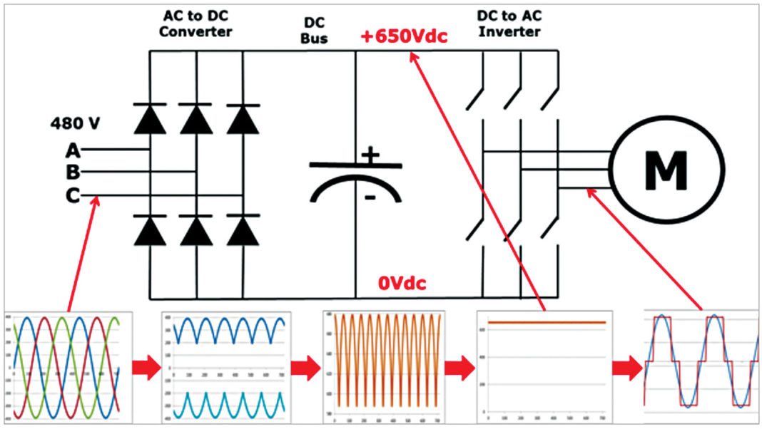
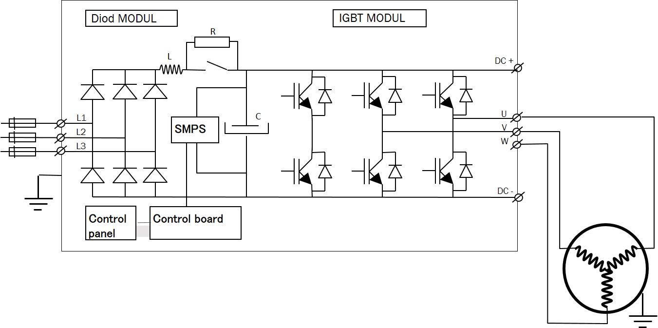
The VFD starter circuit diagram outlines the connections between the VFD, the motor, and the power supply. At the heart of the VFD starter circuit diagram is the VFD itself. This electronic device consists of various modules, such as the rectifier, the DC bus, the inverter, and the control logic.
Single Phase Variable Frequency Drive VFD Circuit
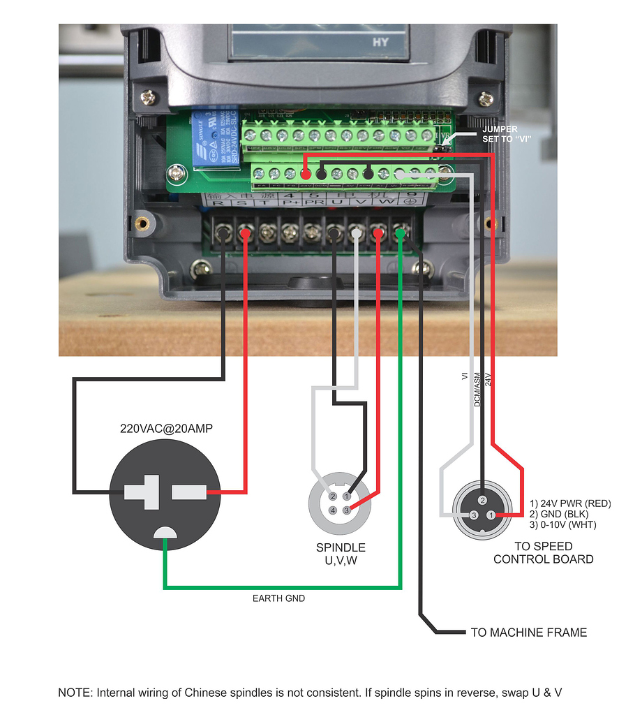
The diagram should reveal several terminal functions: A power supply terminal should be indicated with 24 volts The common ground, or COM A 10-volt output is often provided for the analog speed control device The next set of terminals are Digital Inputs, perhaps 'DI' or 'In' and there are often four to six of these terminals
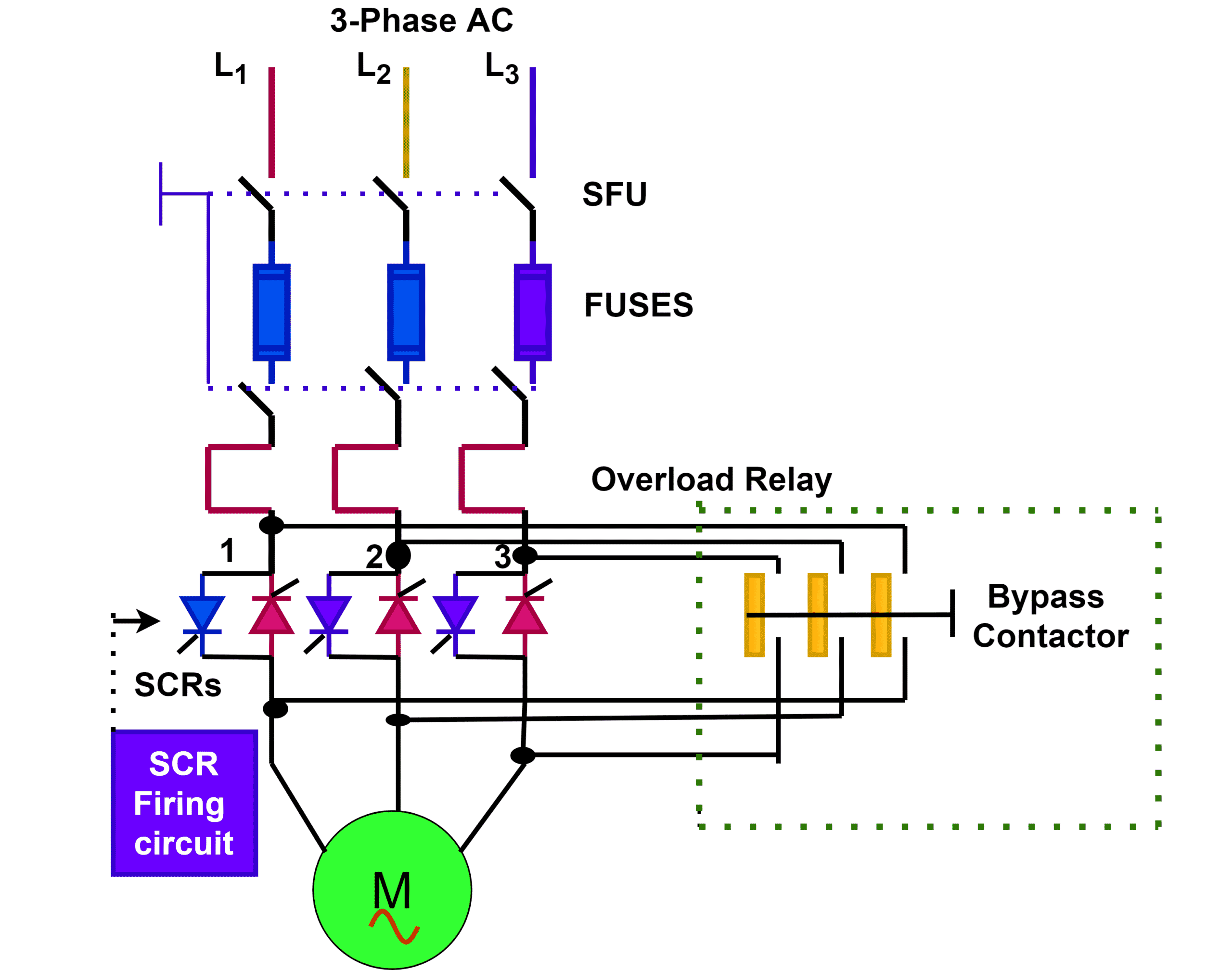
Single Phase Soft Starter Circuit Diagram
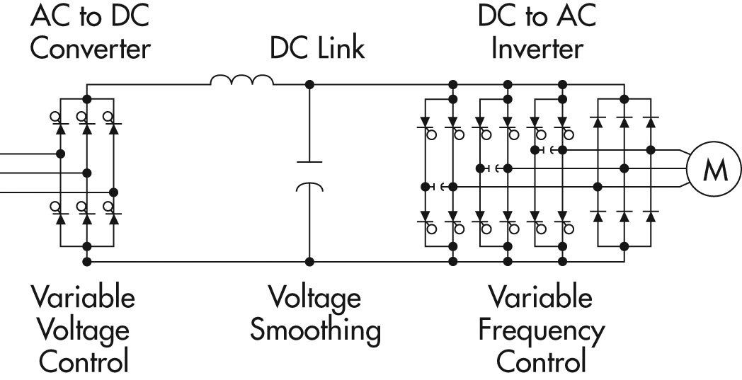
Basic Circuit Block Diagram of a Three-phase VFD Three significant sections constitute the block diagram of a VFD. These sections include The power conversion area. The control section of the microprocessor is responsible for the control of the VFD operations. The power consumption section changes the AC voltage to DC.

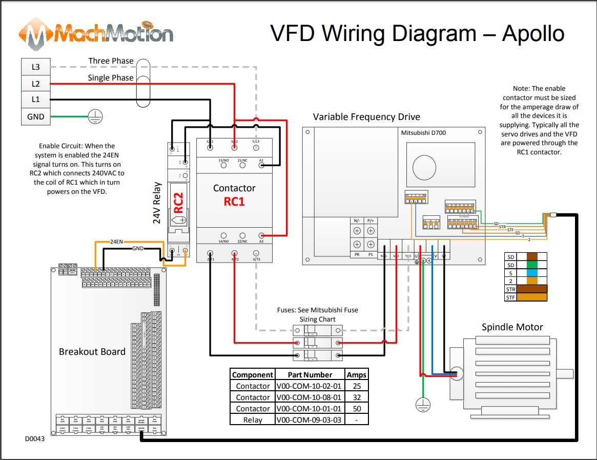
vfd wiring diagrams
vfd motor control circuit diagram and programming In this video, you will learn about how a VFD (Variable Frequency Drive) works and how you can control t.
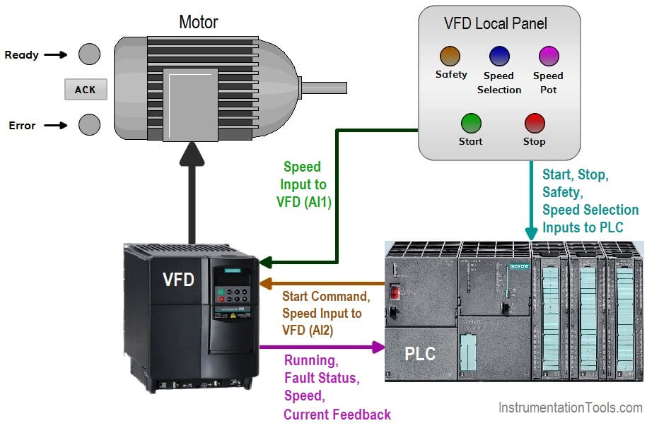
Controlling 3 Phase Induction Motor Using VFD And PLC
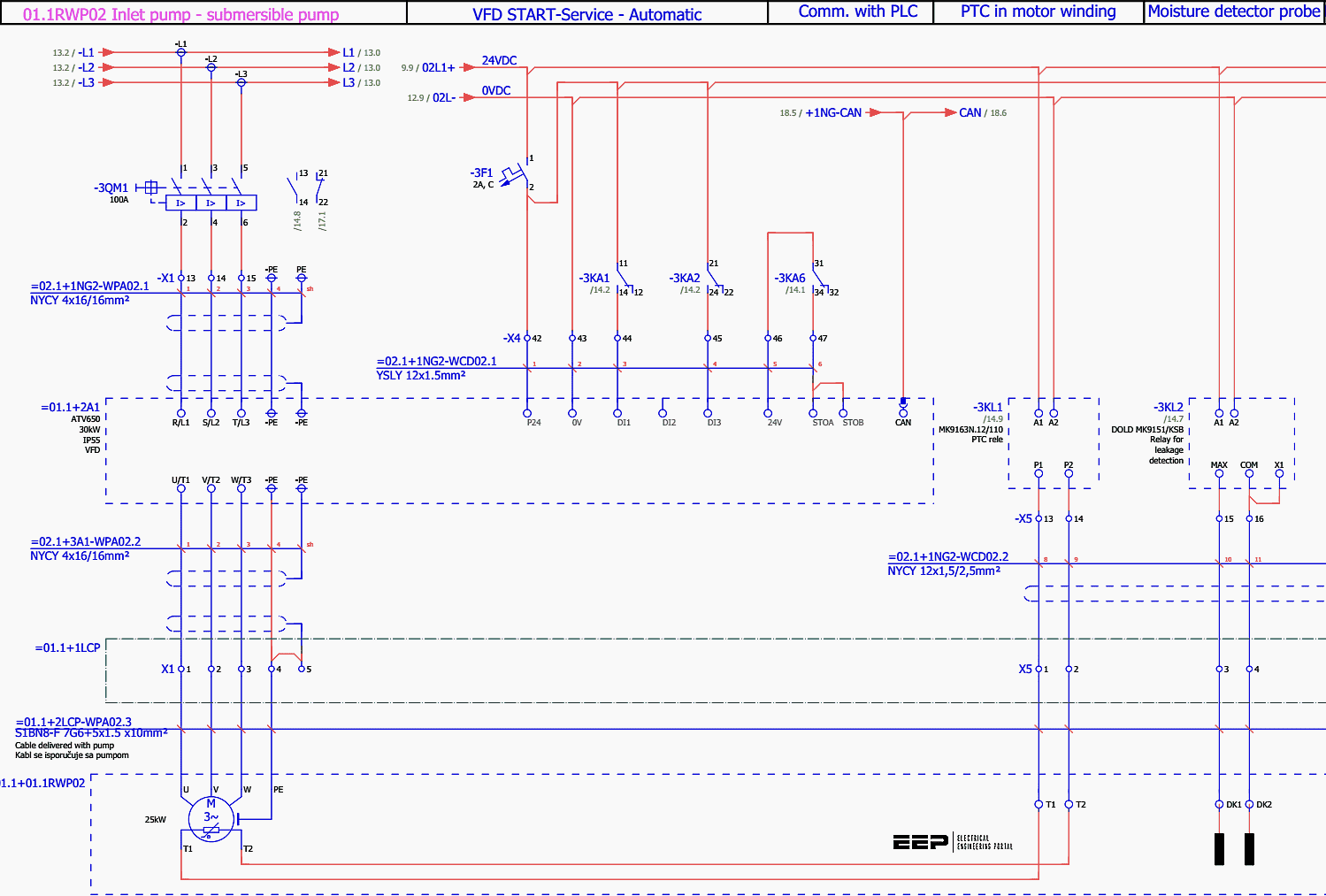
Working Principle VFD Parameters Maximum and Minimum Speed Volts per Hertz Current limiting Start/Stop Source Configuration of Parameters Control Circuit BMS Interfacing Fire Alarm Interfacing Troubleshooting VFDs Manual Mode VFD Testing Remote Mode VFD Testing VFD Power Circuit Diagram for Smoke Extraction Fan

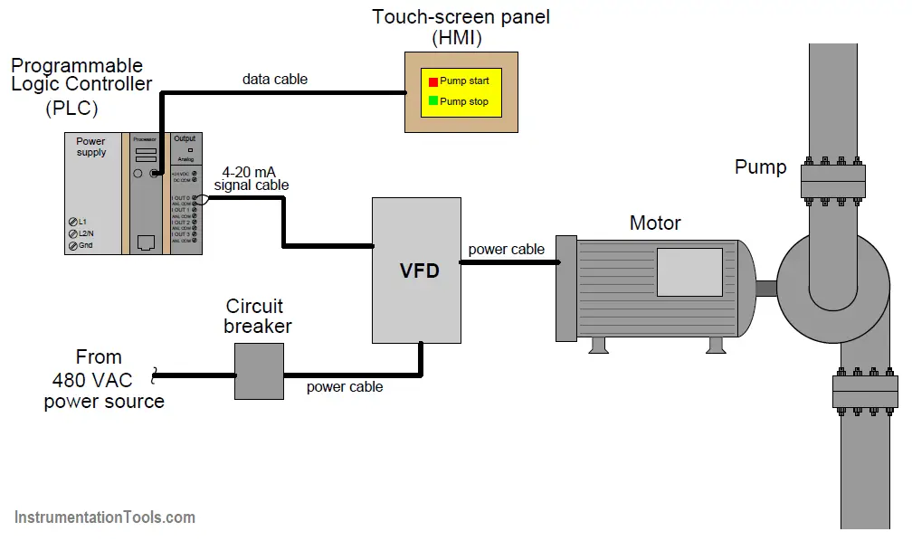
VFD wiring diagram showing power in, power out, and control device... Download Scientific Diagram
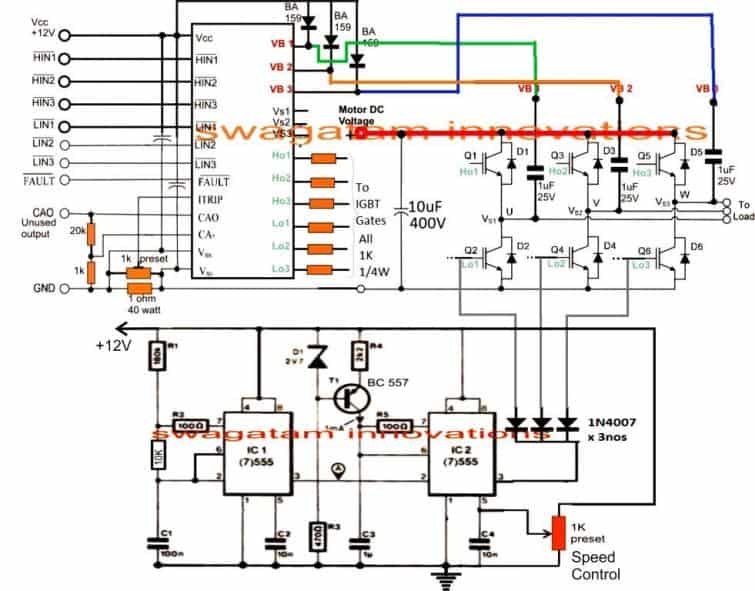
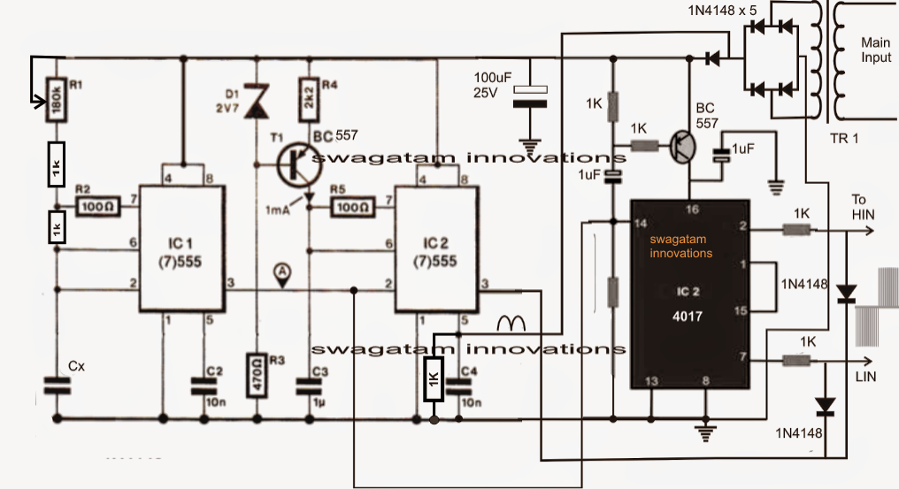
The PWM Controller Circuit You will have to integrate the outputs from the IC 4017 from the above diagram to the HIN and LIN inputs of the following diagram, appropriately. Also, connect the indicated 1N4148 diodes in the above diagram with the low side MOSFET gates as shown in the below diagram. The Full Bridge Motor Driver Update:
Applications Emotron
VFD Control Wiring with Diagram | VFD Wiring Diagram | VFD Motor Control WiringIn this video you will learn about VFD Control Wiring with Diagram | VFD Wirin.
Wiring Vfd Motor Control Circuit Diagram Wiring Diagram Schemas
The VFD Control Circuit Diagram is a graphical representation of the circuitry used to control a Variable Frequency Drive (VFD). A VFD is an electronic device that is used to control the speed and torque of an alternating current (AC) motor.
20 Beautiful Leeson Motor Wiring Diagram
Download scientific diagram | VFD wiring diagram showing power in, power out, and control device connections. Readers should consult and follow the VFD and motor manufacturers' wiring diagrams and.
3 Phase Motor Vfd Circuit Diagram
VFD Control Wiring Diagram | How to Wire a VFD | Variable Frequency Drive#Learning_Engineering #Learning_Engineering_Bangla #Learning_Engineering_Institute.
Vfd Control Wiring Diagram 4K Wallpapers Review
A VFD is designed to control the speed and torque of an electric motor by varying the input voltage and frequency. The circuit diagram of a VFD consists of several key components that work together to achieve this control. At the heart of the VFD circuit diagram is the rectifier, which converts the incoming AC power into DC power.
